2019年12月30日星期一

Working of the Stepper Motor Driver Circuit

The working of this analog Stepper Motor Driver circuit is very simple. We will see a step – by – step working explanation.First, the 555 Timer IC is configured as an Astable Multivibrator i.e. it acts as a square wave generator.

Based on the position of the Potentiometer, the frequency of the square wave will vary anywhere between 7 Hz to 340 Hz.

This square wave is given to the CD4017 Counter IC as its Clock Input. For every positive transition of the clock signal i.e. a low to high transition, the counter output advances by one count.

For first positive transition on clock, Q0 will be high, for second positive transition, Q1 will be high and so on.

Since we need only 4 outputs, the fifth output i.e. Q4 is connected to the Reset pin so that the counter will reset and the counting starts once again.

The outputs of the Counter IC CD4017 are given to 4 different transistor, which are in turn connected to the 4 coil terminals of the Stepper Motor. We can understand better from the following diagram.

Working of the Stepper Motor Driver Circuit

Assume the points A, B, C and D are the contacts of the coils connected to the transistors. The common wire in the stepper motor is given to 12V supply.

When the first clock signal is applied to the CD4017, Q0 becomes HIGH. This will turn ON the corresponding Transistor.

As a result, the supply from the common wire goes through point A to ground. This will energize the coil and acts as an electromagnet. The rotor will get attracted and turns to that position.

During the second clock pulse, output Q1 become HIGH and as a result, the transistor associated with it is turned ON. Now, the current flows from common wire to GND through point B.

Hence, this coil will be energized and turns in to an electromagnet. This will further rotate the rotor. This process continues and depending on the frequency of the clock signal, the speed of rotation of the stepper motor varies.

Advantages
A DIY type Stepper Motor Driver is designed here that can drive Unipolar Stepper Motors.
By using this stepper motor driver, we can avoid costly dedicated Stepper Motor Driver boards.

Disadvantages
This design is not an efficient one.
Requires a lot of complex wiring for a small application. 


2019年12月12日星期四

¿Por qué motores de avance por pasos?

Las primeras pruebas caseras con motores se suelen hacer con los de corriente continua (CC), del tipo que se usan en los juguetes. Estos motores giran libremente y a una velocidad alta. Cualquier intento de lograr que uno de estos motores gire una cantidad acotada de recorrido, como por ejemplo dos vueltas, es imposible. Los motores no giran enseguida a una velocidad conocida: hay que calcular un tiempo de arranque, porque la inercia no les permite llegar a la velocidad normal de inmediato. Y cuando se les corta la alimentación continúan girando, también por inercia.

Note el lector que no hablamos de pedirle a uno de estos motores que se mueva sólo una fracción de una vuelta, como por ejemplo un cuarto de revolución, o un valor así. Esto sería aún más difícil de lograr.

¿Por qué motores de avance por pasos?
23HS22-2804S

Lograr que un motor común de corriente continua gire una fracción de vuelta o una cantidad precisa de vueltas no es sólo muy difícil, es prácticamente imposible. Aún si se controla con extremada precisión la corriente necesaria, buscando fijar con exactitud el tiempo de arranque y detención del motor, de todos modos al cortar la corriente la armadura no se detendrá, ya que continúa moviéndose por inercia, y esta inercia tendrá un valor muy difícil de determinar, ya que dependerá del peso del rotor, la fricción del eje sobre sus cojinetes, la temperatura de las bobinas, núcleos de hierro, imanes y la del propio ambiente, y otras variables del entorno y de la construcción.

     
Agregando engranajes para la reducción de la velocidad se logra atenuar el problema. De todos modos, sigue presentándose el problema de la inercia, lo que producirá un error de posición, aunque disminuido por el factor de reducción de los engranajes. Y se agrega ahora la fricción combinada del juego de engranajes, o sea mayor dificultad para cualquier cálculo.

La manera de lograr una posición precisa con motores de corriente continua es utilizarlos en una configuración de servo. Así funcionan los servomotores que se usan en modelismo (stepper motor for 3d printer ), que constan de un pequeño motor de CC, un juego de engranajes de reducción, un mecanismo de realimentación (que usualmente es un potenciómetro unido al eje de salida) y un circuito de control que compara la posición del motor con la que se desea lograr y mueve el motor para realizar el ajuste.

https://forum.derivative.ca/t/hokuyo-laser-scanner-support/7935/18
http://forums.framboise314.fr/viewtopic.php?f=57&t=5463&p=33244


2019年12月9日星期一

Why do you use a stepper motor?

Easy to use: 34%
Inexpensive: 17%
Simple operations:16%
No need for tuning: 12%
Other: 21%
*# of questionees: 258 (multiple answers allowed)/ researched by Oriental Motor

Key Points: Ease-of-Use, Simple Operations and Low Cost

According to the survey of hybrids stepper motors users, many favor stepper motors for their "ease-of-use," "simple operations", and "low cost" derived from the structure and system configuration. It makes sense that many users find such positive aspects in stepper motors, thanks to the simple structure and system configuration.

Point 1

Fantastic Stopping Accuracy!
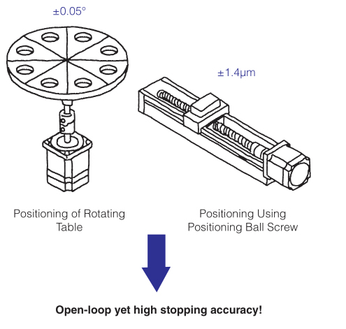
For example, when converting stopping accuracy ±0.05° of a stepper motor to the ball screw mechanism:
Operating Conditions:
• Motor: RK II Series
• Lead of ball screw: 10mm Stopping Accuracy: ±1.4μm
Generally, accuracy of a ground ball screw type is ±10μm. When using a rolled ball screw type, its accuracy declines to ±20μm, indicating that the stopping accuracy of a stepper motor is much higher than that of ball screw types.

Point 2

Excellent Mid/ Low-Speed Range!
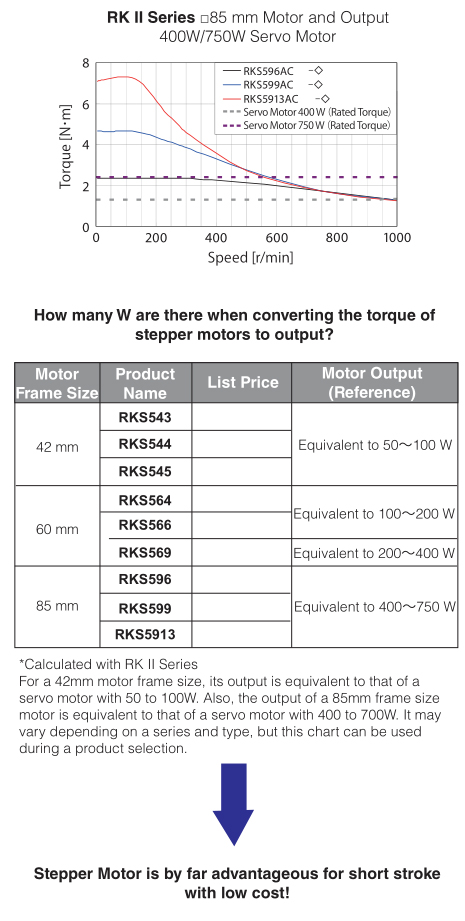
Example: Torque of a motor frame size 85 mm is equivalent to a rated torque of a 400 W servo motor when 1000 r/min.
Torque in an even lower speed range can be up to 5 times higher. For a short- distance positioning, having high torque in the mid/low-speed range is essential.
Impressive "Stopping Accuracy," "Mid/Low-Speed Range" and "Responsiveness"
Stepper motors have remarkable stopping accuracy, and accurate control with open-loop is possible. For example, when using the RK II Series for positioning of a rotating table, its stopping accuracy is within ±0.05 degrees (with no load). Because stopping position errors do not accumulate between steps, high accuracy positioning is possible. The structure of the stepper motor, which requires no encoder, allows for the simple drive system and low cost.

High Responsiveness and Excellent Synchronization

The third remarkable feature of stepper motors is the responsiveness. The open-loop control, which sends one-way commands to the motor, has a very high follow-up mechanism toward commands. 

Suitable Applications!

Other than an inching applications with frequent starting and stopping, stepper motors are suitable for positioning of image check processors that dislike vibrations, cam drives that would be difficult to adjust with servo motors, and low rigidity mechanisms such as a belt drive. Furthermore, cost is reduced significantly by replacing a ball screw drive to a belt drive.

Cost Reduction and the Advantage of Great Features

Besides cost reduction, stepper motors have many advantages in terms of performance. I hope this article provides an opportunity for those who have routinely selected servo motors to start considering stepper motors as their options. On the followong pages, detailed information of stepper motors, such as basic structure, system and example applications, is introduced for those who want to learn more about stepper motors.

Operation & Structure

A stepper motor rotates with a fixed step angle, just like the second hand of a clock. Highly accurate positioning can be performed with open-loop control thanks to the mechanical structure within the motor.