2019年11月23日星期六

Nema 17 motor case and gearbox for 3520 Motors

Hey everyone;

Today a few of us over on the discord channel 3 were discussing how to gear down small BLDC motors and it was suggested that we move the discussion over to here so that more people can join in.

So first things first:

Why gear down small BLDC motors? Why not just use a lower KV motor?
Small BLDC motors (e.g. a 3520 motor, which is 35 mm in diameter, 20 mm long) are only available with moderate KV values of about 420 and larger. This gives them a relatively high top speed compared to their bigger brothers but low torque. Lower KV values are available as gimbal motors but their high winding resistance means you can only drive them at a couple of amps, resulting in even less torque. In theory you could make a very high voltage odrive (> 100 V) but I’m told that high current, high voltage MOSFETs are very expensive and therefore impractical.

By gearing down a motor you also increase the torque, increase your effective encoder resolution and reduce the apparent effects of cogging torque.

Why not use a stepper motor?
You can! Here is a 4.5 N.m hybrid stepper motor and it’s motor driver for comparison. The motor is the same as this model 22 ($48 USD).
IMG_20171217_175901
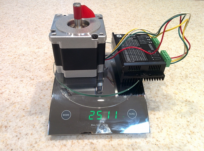
It’s not exactly small being a NEMA 34 motor light weight at 2.5 kg. It’s high coil inductance and high effective pole count also mean that its torque falls off rapidly as you increase speed. It’s also difficult to drive a stepper above ~1000 rpm open loop as I believe you run into problems when you hit certain resonance frequencies. This all results in a relatively low peak power output due to a limited top speed.

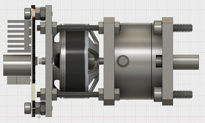
For comparison the design shown below is for a ~4 N.m, 2000 rpm servo motor with integrated drive electronics (odrive one concept) and 21217 counts per rotation on the output. It would also only weigh about 0.5 kg, would fit in a NEMA 17 form factor and the cost of the parts minus electronics (cost TBA) would be around $50 USD with volume.

Odrive one with gearbox - no L bracket

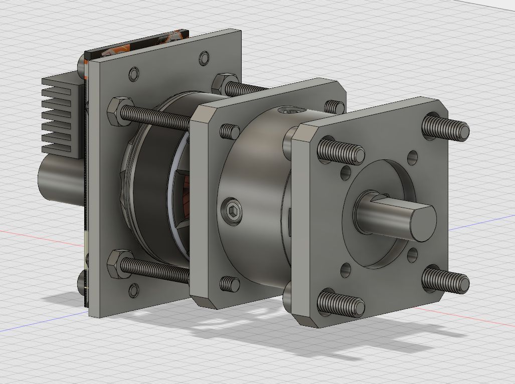
It works by taking the ‘odrive one’ single axis electronics concept describe here 25 which will be able to supply 40A continuous and 80A peak and use a 4096 count per rotation magnetic encoder. This is used to power a ~200g 3520 size motor ($22 USD) with 420 KV for a maximum speed of ~10,000 rpm at 24 V and an estimated 0.8 N.m of torque. The planetary gearbox ($15.5 USD) gives a 5.18:1 reduction to give the 4 N.m output at 2000 rpm for a peak output power of around 650W with conservative estimates for losses.

The power electronics are mounted on the rear. The back of the motor shaft has a magnet located on it which is position next to the magnetic rotary encoder chip on the pcb. The motor is coupled to the back plate which is then connected via four bolts to the gerabox which has a nema17 mounting hole spacin.
Odrive one with gearbox side view - no L bracket

Of course there are drawbacks to this approach. A stepper motor can operate at its rates torque all day without having to worry about overheating while this servo design will let the smoke out after about a minute at full torque. However, for a lot of application the effective duty cycle is low enough that this is not a problem. A good use-case would be something like a CNC mill where the peak load is only seen during brief moments of rapid acceleration and deceleration. A bad use-case would be trying to hold up your robot arm against gravity with this drive or using it to power your ebike flat-out up a hill.

Odrive one with gearbox - with L bracket

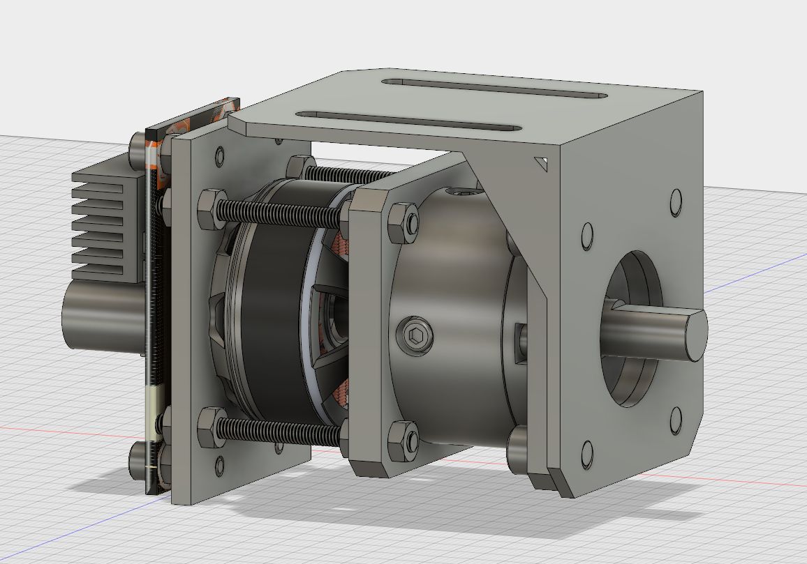
If you would like to check out the model you can find a copy here 15. I mostly just modified existing parts that were available on grabcad so credit goes to those people. Nuts 1, stepper motor gearbox 26, terminal block 2, motor 6, L bracket 2.

@Wetmelon has been working on a similar setup for the larger and more powerful N5065 motor over in this thread 18 in case anyone is interested in going one size up.

This is only a rough first pass on the idea so if anyone has any thoughts at all (good or bad) I would love to hear them.

How to Choose the Right Stepper motor for Medical Use

When selecting a stepmotor for a medical device, engineers need to consider many factors. For example, a systolic pump may require accuracy in a small package while lab devices, such as a blood sampler, may need to be exceptionally quiet. Although requirements for stepmotors vary from device to device, there are several factors that should always be considered.

Making it small
In terms of size, stepmotor manufacturers adhere to various NEMA frame sizes. NEMA is the industry standard governing motor dimensions, including the size of the front flanges used to mount motors to devices. NEMA sizes for stepmotors range from NEMA-8 to NEMA-42 Motor. For comparison, NEMA-8 motors with 0.8-in.2 front flanges generate about 2 to 3 oz-in. of torque, while NEMA-42 motors have 4.2-in.2 front flanges and output over 2,000 oz-in. of torque.

How to Select the Right Stepper motor for Medical Use


Pinpoint accuracy
Stepmotors rotate in terms of degrees. Each step can be in increments of 1.8°, 0.9°, or even 0.45°. This is the inherent and natural step the motor takes. Motors can also be microstepped or forced to take even finer increments. For example, a 0.9° motor can be made to step every 0.45°, which is called half-stepping the motor. And 64× microstepping a motor divides the 0.9° into 64 steps of 0.014°. Microstepping is usually handled by the driver electronics.

Smooth, quiet steps
Stepmotors can stop and hold position at any location a program tells it to. But as their name indicates, they take steps when moving. For example, to complete a full revolution, a 1.8° motor takes 200 steps. A stepmotor’s rotational speed is stated in terms of step pulses, or hertz, and is considered a frequency. At certain speeds, stepmotors resonate and vibrate loudly, and this vibration translates into jerky motion. The loud noise is due to the rotational frequency matching the motor’s inherent resonant frequency, which every stepmotor has. And the resonant frequency is generated with each step the motor takes. But there are ways to either eliminate or diminish the noise a motor makes.

Reliability and quality
When looking for reliable stepmotors, engineers often request MTBF (mean-time-between-failure) data to ensure the potential motor will last a certain number of cycles. Stepmotors typically have an MTBF of over 20,000 hr of continuous operation. When stepmotors operate at their bearings’ rated axial and radial loads or less with temperatures kept to less than 50°C, stepmotors usually last 20 years, assuming a 50% duty cycle.

So, whether your application involves making intricate cuts within a patient’s eyes, pumping critical bodily fluids, or any other type of medical application, taking a motor’s size, accuracy, smoothness of motion, noise level, quality, and reliability are a must.

https://forum.duet3d.com/topic/13002/thread-holes-on-nema-17-motor-arent-deep-enough

2019年11月21日星期四

Stepper Motors For CNC Routers

Generally, you are going to need at last NEMA23 from 175oz/in upwards unless your machine is very small such as a CNC engraver. These are quite often used for making Printed Circuit Boards(PCB) and if you check the description they will say only for soft materials.

Stepper Motors For CNC Routers


So let’s look at a couple of examples.

For routers, the cutting material plays a big part in our decision. Harder materials will need a more powerful stepper because the cutting bit is being driven into the material.

The WorkBee from Oyostepper in the China which is based on the OpenBuilds design. It uses NEMA23 of 175 oz/in. If you check some of the offerings on eBay for 6040 CNC routers you’ll quite often see in the description 57 size motors, which is the metric equivalent of 2.3 inches or NEMA23’s and these usually come with 175-200oz-in motors.

If you intended to cut very hard materials then high torque steppers motors will be required usually around 300-400 oz/in and you may need to go up to NEMA34 and you will need a strong frame to support that.

How to choose Step Motor for CNC Machine

2019年11月19日星期二

When stepper motor generates vibration and noise, how to do it?

When the stepper motor is running, if there is obvious noise and vibration is caused to the stepper motor, the following steps is helpful to troubleshooting:

It really does matter whether the stepper motor is matched with the driver. If not, it may be useless to take following steps such as division, drive current and speed adjustment. It is suggested to buy a set and ensure it is qualified when selecting the stepper motor and driver.

Now the stepper motor driver is divided into digital and analog. The noise of the analog stepper motor driver is large while it is basically no for the digital one, generally because one DSP chip is added to the digital driver to optimize the stepper motor drive. Therefore, to ensure the noise and vibration is as small as it is, it is advised to use the digital stepper driver.


Correctly adjust the subdivision and current of the stepper motor driver. The larger the subdivision is, the smaller the change amplitude of coil in motor is. That is, the noise is mitigated. As for subdivision, it is advised to set it as 8 and above. Under the circumstance that there is enough torque to drive the load for the stepper motor, it is also necessary to reduce the driver current. The smaller the parameter set, the small the change amplitude of the coil in the motor is.
Correctly set the stepper motor’s acceleration and deceleration and highest rotational velocity. It is easy to generate additional noise during the acceleration and deceleration of the stepper motor. The solution is to increase the acceleration and deceleration of the stepper motor appropriately under the circumstance that acceleration and deceleration doesn’t cause losing step.
3. Why the stepper motor doesn’t rotate or move back and forth after it is powered?
If the stepper motor doesn’t rotate sometimes or move back and forth after starting, the following inspection for troubleshooting can be taken into considerations.

When selecting the stepper motor, considering whether the working torque is large enough and whether it can drive the load or not. Therefore, it is recommended to select the motor which has 30%-50% larger torque than the actual needs, because the stepper motor cannot rotate under overload, or causing losing step even if it overloads just one second. More seriously, the stalling or repeated and irregular motioning on the spot will be caused.

Check whether the input stroke pulse from the upper controller is correct, or whether the input frequency is high and maybe it is filtered by opt coupler.

Check whether the start frequency is too high and whether acceleration process is set in the start procedure. It is better to begin accelerating to the set rate from the start frequency regulated for the motor. No matter the acceleration time is very short, or it cannot be stable.

When the motor is not fixed, it is normal that such situation like the motor intense resonance may emerge sometimes. Therefore, the motor should be fixed.
Considering whether there is lack of phase. If so, the motor will vibrate and won’t rotate normally. As for 2-phase stepper motor, the motor also cannot work normally in case of wrong phase wiring.

https://socialsocial.social/user/xiangzhao32/
http://biznas.com/Biz-postsm60751_Stepper-Motors-For-Hot-Wire-CNC-Foam-Cutters.aspx#post60751


2019年11月14日星期四

2 Phase and 3 Phase Motors You Should Know About

Oyostepper offers several families of hybrid step motors with a different number of phases and step angles. Each has a combination of advantages that are better suited to specific applications.

• 2 Phase - 1.8 degree step angle
This is the most popular step motor. It has a great combination of torque, speed and accuracy. Due to their high volumes, drives for 2 phase motors are very common and economical.

The basic method of control is to have the motor make one full step as the drive applies full current to the motor windings. This causes the motor to move in full step increments. When the motor is stepped at different rates it may make a distinctive sound and can vibrate (resonate) at certain speeds. This is not a problem for most applications. If it is an issue, motors can be controlled with micro-stepping drives that smooth motor torque. And many times, resonate speeds can simply be avoided by programming the drive.

Oyostepper offers 2 phase 0.9 degree step motors, and three phase 1.2 degree step motors, for applications that need even more accuracy, or motion that is very smooth and quiet.


• 2 Phase - 0.9 degree step angle
Because each step moves only ½ the distance of 1.8 degree motors, these motors have higher accuracy and very smooth movement. The drive for this motor is exactly the same as the 2 phase, 1.8 degree motors. For the same speed, these motors must have a step rate that is 2 times that of a 1.8 degree motor. This higher step rate leads to less torque at high speeds. However, for many applications high speed is not needed, or higher voltage drives can be used to increase torque at high speeds.

2 Phase stepper motor and 3 Phase stepper motors, 0.9 degree, 1.2 degree, 1.8 Degree step angle
14HK0 Shown Full Size
An example of a good application for 0.9 degree motors are security cameras. These motors allow the camera to be precisely moved without "camera shake" which causes the picture to vibrate. Oyostepper' offers small encapsulated sizes that reduce camera package size, and helps withstand the outdoor environment.

• 3 Phase - 1.2 degree step angle
The use of three phases inherently helps to reduce torque ripple and smooth motor performance. 3 phase motors require a 3 phase drive that is different than the drive for 2 phase motors. As compared to the 1.8 degree two phase motors, the low speed torque is somewhat less. But design improvements introduced by Oyostepper', minimizes this difference. High speed torque can also be comparable. In addition, Oyostepper' size 24 three phase motors are available with PowerPlus technology, for maximon torque. 3 phase motors are used where maximum performance, and very quiet, smooth precise movement is need. An example of a good application for three phase motors is in performance lighting. These spotlights lights need quick movement, and quiet operation so as not disturb the performance.

http://www.apsense.com/article/whats-the-difference-among-4wire6wire8wire-step-motor.html

2019年11月11日星期一

Troubleshooting of getting speed up on a Nema 34 Motor

Hi Guys, i was hoping someone on here could help me work out a issue I'm having.


I have a ESAB waterjet machine. It has 3 heads the first two have failed. This is a very expensive yet older machine, so rather than pay to fly in a tech, put him up in a hotel, pay for $1000's servo drives to be replaced. I decided to replace the first head AC servo motor with a nema 34 stepper motor controlled by an arduino. I have it installed and all my code and buttons work, I'm using a very primitive coding system to pulse the microstepper 1 step every time the button is pressed. It takes 1400 steps to do a revolution. If I hold the button it will just turn until I let go. I control the speed by changing the delay. The lower the delay the faster the rotation. The longer the delay the slower. So to get my speed up to a usable speed I had to set it to 90 microseconds.


I'm using a SainSmart CNC Micro-Stepping Stepper Motor Driver 2M542 Bi-polar 2phase 4.2A Switch.

I'm using a 960 oz-in NEMA 34 Motor capable of 7 amps of current.

I'm using a NEWSTYLE 24V 15A Dc Universal Regulated CNC Switching Power Supply 360W.

I'm using a Arduino Nano as well.


Now I know my microstepper is only capable of 4.5 amps of current but that is plenty to lift and lower my head. I was actually going to use a Nema 23 but the nema 34 was a direct replacement. I also know the Nema 34 and microstepper would be better suited to a 48v power supply but for now the 24v should be fine.


So the Problem. The way I set it up is 4 buttons, one slow up/one slow down and one fast up/one fast down. It does work, but I can't get my speeds as fast as i want. Also I know the machine is not moving with the torque I feel it should. If I try to change my delay down to say 10-75 microseconds the motor makes a noise and doesn't move. It's not missing steps and it's nowhere near using much in the terms of current. Maybe 1.6 amps at 600 microsecond delay and 1.2 amps at 90 microsecond delay. I'm sure there is a better way to code this using the accelstepper function library but i haven't got that far yet and this would work fine for me if I could get the speed up. I've seen this motor do 1400 ipm rapids on a cnc router so I know it's capable.


I'm wondering if by pulsing every 90 microseconds am I pushing too much code through the arduino causing it to stall out. Or is it possible my power supply is just to small. Regardless i do have a larger one on order. But meanwhile I was just curious what the experts thought. And also this code might help some people get a microstepper working in the simplest possible way IMO.


Thanks for any help in advance. I'm very new to the Arduino so take it easy on me. I'm trying.


As for my code here it is:

Troubleshooting help getting speed up on a Nema 34


#define DISTANCE 1 //Set the amount steps per button press, if set to 1 and held it will rotate forever at one step increments, if set to 1600 it will do one revolution per press//


int StepCounter = 0;
int Stepping = false;
int SteppingFast = false;

void setup() {
 pinMode(8, OUTPUT); //direction on microstepper//
 pinMode(9, OUTPUT); //pul on microstepper//
 digitalWrite(8, LOW);
 digitalWrite(9, LOW);

 pinMode(2, INPUT); //button slow up, not positive on these//
 pinMode(3, INPUT); //button slow down, machine is at work//
 pinMode(4, INPUT); //button fast down, will check later//
 pinMode(5, INPUT); //button fast up//
}

void loop() {
 if (digitalRead(3) == LOW && Stepping == false)
 {
   digitalWrite(8, LOW);
   Stepping = true;
 }
 if (digitalRead(2) == LOW && Stepping == false)
 {
   digitalWrite(8, HIGH);
   Stepping = true;
 }

 if (Stepping == true)
 {
   digitalWrite(9, HIGH);
   delayMicroseconds(600); //changing to delaymicroseconds allows the loop to run faster acting like a faster rpm//
   digitalWrite(9, LOW);
   delayMicroseconds(600);

   StepCounter = StepCounter + 1;
 }
 if (StepCounter == DISTANCE)
 {
   StepCounter = 0;
   Stepping = false;
 }

 if (digitalRead(4) == LOW && SteppingFast == false)
 {
   digitalWrite(8, LOW);
   SteppingFast = true;
 }
 if (digitalRead(5) == LOW && SteppingFast == false)
 {
   digitalWrite(8, HIGH);
   SteppingFast = true;
 }
 if (SteppingFast == true)
 {
   digitalWrite(9, HIGH);
   delayMicroseconds(90); //changing to delaymicroseconds allows the loop to run faster acting like a faster rpm//
   digitalWrite(9, LOW);
   delayMicroseconds(90);

   StepCounter = StepCounter + 1;
 }
 if (StepCounter == DISTANCE)
 {
   StepCounter = 0;
   SteppingFast = false;
 }
}

https://www.dopr.net/oyostepper

2019年11月1日星期五

50-56 N⋅cm Stepper Motor – The "Big Beef" of NEMA 17 Motors

Stepper motors are relatively simple mechanisms: A series of electromagnetic coils are activated in a specific sequence to spin a motor shaft a precise number of degrees. The NEMA specification is what allows stepper motors to be identified, and references the size of the faceplate of the motor.

Nema 17 Stepper Motor Bipolar 0.9 deg 46Ncm 2A 2.8V 42x42x48mm 4 Wires(17HM19-2004S)
17HM19-2004S

This variety of stepper motors Nema 17 is rather rare in the world of 3D printers, simply because they are almost too big and powerful. Common applications of this motor are for moving extremely large or heavy print beds in Prusa i3 style printers.

Being longer and distinguished than their counterparts, 50-56 N⋅cm motors are rarely used on moving gantries, as their mass causes issues with inertia at higher printing speeds. Typically used in a fixed position, these motors are usually better suited to CNC work than 3D printing applications.

However, if you need to move a large, heavy print bed quickly, like on the Creality CR-10 S4 and S5, then these motors are the ones for you.

NEMA Specifications and Torque Ratings of Stepper Motor
HOW TO CONTROL NEMA17 STEPPING MOTOR BY USING ARDUINO AND A4988 DRIVER